Now that the theory is out of the way, it’s time to highlight some of the zillions of applications for this handy little operation.
If none of this sounds familiar you might want to revisit the first post in the series before continuing.
The dot product is incredibly useful for a TA for two reasons. First, dots allow you to convert between geometric measures and angles without the need for matrices or complex formulae. Second, dots provide an efficient way to project one vector on to another, allowing you to measure distances and quantities relative to an arbitrary axis or vector - a great tool for anything from color conversions in a pixel shader to measuring motion in a complex rig.
Before getting down to cases, a quick reminder of one important side fact we pointed out last time. A cosine dot product can only tell you how different the angle between two vectors is - not what rotations would transform one vector into the other. If you try out this example you’ll see that the dot of
[1,0,0] against both [.5, .866, 0] and [.5, -.866, 0] is .5, which (if you remember your sines and cosines) means the relative angle is 30 degrees. However one of those two vectors is clockwise from [1,0,0] and the other is counter-clockwise from it. The dot, by itself, can’t tell you which one is which. Don’t forget that bit!As I mentioned in the last article, the math for dots is trivially simple. Maxscript includes vector math functions by default, as does MEL, but vanilla maya.cmds does not. If you want to experiment with examples mentioned here in Maya python, you can importpymel.core.datataypesand use theVector. I’ve also put a simple vector module up on Github that works inMaya.cmds. I’ll be using that for these examples but translating between MXS, Pymel, and cmds should be a no-brainer.
rigging
One of the most common tasks in rigging is wrangling information into the correct frame of reference.This is particularly tough when dealing with angular data, since angles are often presented in the form of Euler angles whose numeric values can vary unpredictably and which are therefore hard to use in expressions or code. Here are a few examples of how dot’s can help riggers get angular information while avoiding the Euler bluesThe Bends
Dot’s are an excellent way to measure the extension of a limb, without relying on an Euler value which might be affected by local axis orientations, joint orients, or rotated local axes. Here’s an example that gets a reliable value for the extension of an arm (note: this is vanilla maya, you could do it more succintly with Pymel but it’s a better illustration to do it from scratch)shoulder_pos = cmds.xform('r_shoulder', t=True, w=True) elbow_pos = cmds.xform('r_elbow', t=True, w=True) wrist_pos = cmds.xform('r_wrist', t=True, w=True) bicep_vector = (Vector3(*elbow_pos) - Vector3(*shoulder_pos)).normalized() forearm_vector = (Vector3(*wrist_pos) - Vector3(*elbow_pos)).normalized() elbow_bend = Vector3.dot(bicep_vector, forearm_vector)
then
arm_extension will be 1 at full extension and 0 when the arm is bent back completely on itself (ouch!). You can map use this extension value to drive muscle deformations, blendshapes, or other behaviors without worrying about th underlying Euler values or converting from angles to linear ranges.Leaning In
It’s often useful to have a general idea what a character’s whole body is doing, rather than focusing entirely on individual joint positions and orientations. For example, you might want to have rig behaviors turn on when a character is ‘upright’ and off when it it is ‘prone’, or vice-versa. Figuring out the gross orientation is often hard because there are so many bones cooperating to produce the visual effect – and because different animators may use different controls in different ways: animator A may prefer to put all of the big rotations onto a center-of-gravity control while animator B does everything on the pelvis.Dots are great for extracting pose info from the world space position of key bones instead of trying to intuit them from rotation values. For example:
head_pos = cmds.xform('head', t=True, w=True)
pelvis_pos = cmds.xform('pelvis', t=True, w=True)

# how upright is the character’s body?
body_vector = (Vector3(*head_pos) - Vector3(*pelvis_pos)).normalized()
upright = Vector3.dot(body_vector, Vector3(0,1,0)) # for a y-up world
Here upright will be close to 1 for an upstanding character, close to 0 for a prone character, and close to -1 for an upside down character (eg, during a handstand). This version tracks the pelvis-to-head vector so it will respond to things like a hunched-over spine; but one of the nice side effects of vector math it that you can easily ‘weight’ different elements as you put together your vectors. For example:
chest_pos = cmds.xform('spine_3', q=True, t=True, w=True)
head_and_chest = (Vector3(*chest_pos) * 2 + Vector3(*head_pos))  / 3.0
body_vector = (Vector3(*head_and_chest) - Vector3(*pelvis_pos)).normalized()
upright = Vector3.dot(body_vector, Vector3(0,1,0))
Looky here
You don’t always have to use positions to drive dot-product calculations. You can always get the local orientation of a transform by looking at it’s matrix (the exact reason for this will be shown in a later posting, for now take it on faith). This allows you to see how closely a given object is oriented towards a given vector.For example, something like this will help you figure out if a character’s body is oriented in roughly the same direction as the character’s root bone:
# assuming that the bones are constructed with positive z as 'forward'
world_forward = lambda b: cmds.getAttr(b + ".worldMatrix")[8:11]
root_forward = Vector3(*world_forward('root'))
pelvis_forward = Vector3(*world_forward('pelvis'))
shoulders_forward = Vector3(*world_forward('spine_3'))
head_forward = Vector3(*world_forward('head'))
# get a weighted average of the pelvis, shoulder and head directions
composite = ((pelvis_forward * 3) + (shoulders_forward * 2) + head_forward) / 5.0
# flatten the composite and root vectors into 2 dimensions:
composite = composite * Vector3(1,0,1)
root_forward = root_forward * Vector3(1,0,1)
orientation = Vector3.dot(composite.normalized(), (root_forward.normalized())
A value of 1 would have the character facing precisely along the same direction as it’s root bone in 2D. This kind of thing is especially useful when you’re trying to manage a lot of animations which need to begin and end in similar poses - you can quickly check the overall posture of a lot of characters without too much detailed analysis to spot problems before going in and looking at the troublesome ones for hand fixing.
shaders
Even more than rigging, shader authoring frequently involves a return to the math fundamentals. The most familiar example of the dot product in shader writing is the Lambert rendering equation which we discussed in the last post. However, you can get a variety of other handy effects from the dot inb shaders. The key is to find the right set of vectors to work with.For example, if you dot a surface normal against the vector along which the camera is looking, the result will tell you how directly surface is facing the camera. This allows you to create a fresnel or edge-highlighting effect.
Here’s a snippet of a very minimal Unity shader that illustrates the principle:
void surf (Input IN, inout SurfaceOutput o) {
        // a hacky way to get the camera vector…
        float3 cam_vect = UNITY_MATRIX_IT_MV[2].xyz;
        float result = 1 - dot( cam_vect, o.Normal);
        o.Albedo = float3(.5,pow(result, FresnelPower) ,.5);
        o.Alpha = 1;
        }
The only thing worth noting here is the way the result value is being inverted: we want the result number to be close to 1 at the horizon and close to zero where the camera normal and the surface normal are aligned, which is the reverse of what the dot would normally give us. By raising the result value to a higher or lower power (using
pow) we can sharpen or soften the effect; since it the result value should always be 1 or lower a higher power will result in a smaller result value and thus a tighter highlight as you can see in the images. |
| The dotting the camera vector against the surface normal produces an edge highlight fresnel-style effect. The size of the effect can be tweaked by raising the dot product value to a higher or lower power. |
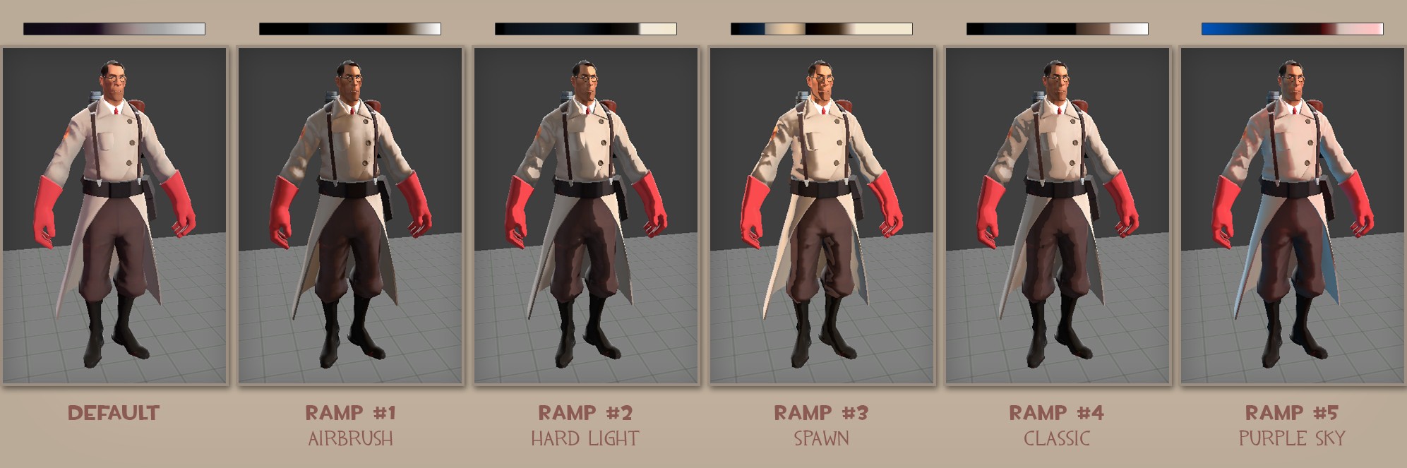
You can re-map that dot product in other ways as well. The popular Team Fortress 2 shader, for example, takes the dot between the light and the surface normal - which, of course, will range in value from -1 to 1 - and re-maps it onto the range 0 to 1 so it can be used to lookup a color value from a texture. That’s how the game achieves it’s distinctive ‘wrap-around’ lighting:
Both of those uses use the ‘cosine falloff’ intepretation of the dot product, that is, they represent angular differences. However dots have another mathematical meaning: they represent the projection of one vector onto another. One really cool aspect the projective use of the dot is that the logic works in color spaces as well as physical space. For example, a shader writer of can get the luminance of a pixel elegantly like this:
float luma = dot( float3(0.2126, 0.7152, 0.0722), pixel_color);
Which is essentially projecting the color onto a ‘luminance vector’ dominated by green (numbers derived from this) You could use the same trick to identify ‘warm’ colors by dotting against a warm rgb value like (.707, .707, 0) - high dot values will be warm and low dot values will be cool. It takes some meditation to really grok what’s going on (try parsing what’s happening in this example!) but dots can be a very handy trick for navigating color space as well as 3-d space.
Shader writers have one more sneaky use for dots - they can be a cheap substitute for selection functions. Shader authors often have to pack data into vectors for efficiency, but accessing one component of a vector would need an expensive if-then branch in theshader. Dots, however, can let you pick one component out of your vector without using branches. Since the dot of any vector composed of all zeros is of course zero. If one component is a one and the rest are zeros, the result will be the corresponding component of the other vector. Thus:
float3 y = float3(0,1,0);
float3 x = float3(1,0,0);
float3 val = float3(.5, .866, 0);
// dot(x,val) == val.x = .5;
// dot(y,val) == val.y = .866;
tools
It’s easy to see who the kinds of tricks we’ve already laid out for shaders and rigging generalize for tool writing. The dot of a surface normal and a vector is a great proxy for whether or not the a surface is facing something, dots are great for analyzing geometry. For example, A tree-and-rock scattering script can dot the normal of a terrain against gravity to figure out which slopes are too steep for trees, or which areas are bottomland where there ought to be lots of bushes. A terrain editing tool could against a sun vector to identify exposed areas where the grass is yellowed and shady spots where it’s lush and green.As with rigging , the dot also provides a way to check relative orientations. For example, you might need to know if an object has been where another object can ‘see’ it. If you dot a reference vector - such the object’s local X or Z axs - against the vector to a target, you can figure out if the target is ‘ahead’ or ‘behind’ the reference object. For example this function would tell you if the target was within some angle of the forward axis of the observer:
   def target_visible(reference, target, cone-angle = .5_):
        """Is target within <coneangle> when viewed on references' local Z axis?"""
        reference-vector =  cmds.getAttr(reference + ".worldMatrix")[8:11]
        target_pos = cmds.xform(target, q=True, t=True, ws=True)
        reference-pos = cmds.xform(reference, q=True, t=True, ws=True)
        target-vector = (Vector3(*target-pos) - Vector3(* reference-pos))
        return Vector3.dot(target-vector.normalized(), reference-vector.normalized()) <= cone-angle
You could restrict that to one or two axes using the same trick in the rigging example, or use the full cone angle as done here.
As an aside, this brings up the issue of converting between dots and angles. Since the geometric dot product (as always, assuming you’ve got normalized vectors) is a cosine, you can convert it to an angle by using the arc-cosine function (acos in Python and most other languages) like so:
cosine = Vector3.dot(a, b)
angle_in_radians = math.acos(cosine)
angle_in_degrees = math.degrees(angle_in_radians)
The projective function of dots is also useful in tools. For example, you can use a dot to clamp a line to the position of the mouse, even if the line is constrained so that the mouse doesn’t physically rest on the line:
line_vector = Vector2(.707, .707)  # a 45 degree line
line_origin = Vector2(200, 200)    # start drawing at pixel (200,200)
while (mouse.down()):
    line_end = Vector2.dot( Vector2(*mouse.position) - line_origin, line_vector)
    draw_line (line_origin, line_origin + line_end)
Further reading
If this one whetted your appetite and you need to know more, here’s a few links I found handy while reading up:- Chris Evans’ vector math tutorial
- A page on projective dot products, along with an applet that helps you visualize how the projection works
- This post from Wolfire, developers of Overgrowth includes some nice examples of how dots are used in AI and game code (plus a peek at some other concepts I’ll be covering later in this series)
- Update: +Paul Vosper put me on to the excellent Scratchapixel.com
I'll be back on the math trail again as soon as I emerge from my mythical tryptophan coma.
Posts in this series
- Bagels and Coffee (intro to dot products)
- Dots All Folks (dot product uses)
- Dot Matrix (intro to matrices)
- Adventures in the 4th Dimension (translation matrices)
- To Scale! (scale matrices)
No comments:
Post a Comment